Author: John KI7LYP

  • Project Considerations

    A great COVID-19 project might be the installation of a new mobile radio, or to inspect and do some maintenance on an existing installation!

    Installation Items to Think About

    • Never use existing vehicle wiring to power any amateur radio gear. This includes fuse taps and accessory sockets!
    • Factory-supplied 120 volt inverters may cause RFI, and arcing can occur between the springloaded tip of the accessory socket plug and the positive contact inside the socket.
    • Solid wire should never be used in a mobile installation. This includes CAT5 cable often used as a less expensive alternative to factory-supplied, modularized cables.
    • Most mobile transceivers operate on 13.8 VDC. If the voltage drops much lower than 12.2, most transceivers will simply shut off or have lower power and transmission quality issues. Use of #12 gauge wire will work for most installations and prevent voltage drops.
    • Twist-on wire nuts should never be used as a splice.
    • One of the most important requirements for secure terminations, is using the right crimping tool.
    • Using the wrong size terminals such as #12 terminals for #18 wire is a common error. Use the correct size and try to use ring connectors.
    • All connectors should be both crimped and soldered to insure strength and low resistance connections. Try to avoid butt connectors.
    • Insulation temperature rating of vehicle wiring should be at least 90°C (195°F) in the passenger compartment, and 105°C (220°F) in the engine compartment.
    • All exposed wire should be covered with protective split loom.
    • Abrasion resistance is also important. XLP and PVC insulation materials are both acceptable, if they’re rated at the correct temperatures.
    • Correctly installed wiring should be out of sight, protected from abrasion and sharp edges, and positioned in such a way as to eliminate hazards and interference from or to vehicle wiring and controls.
    • Do not use vinyl electrical tape to secure the cables. Although the vinyl may not fail, the adhesive eventually becomes elastic which allows the tape to unwrap.
    • All wiring should be secured to prevent vibration damage to the insulation and/or connection points.

    Power Connection Concerns

    • Some aluminum-bodied vehicles require special installation practices with respect to galvanic corrosion. Check the factory recommended installation procedures.
    • Preferably connect the positive power to the positive battery terminal and the negative lead to the same chassis grounding point as the battery’s chassis ground point and not to the battery negative terminal.
    • The negative lead fuse should not be removed. If the grounding point should lose its integrity, excessive current could flow through the transceiver’s negative lead.
    • It should be noted that, in some cases, the battery’s chassis grounding point is inaccessible. If this is the case, attach the transceiver’s ground connection as close as possible.

    Maintenance Items to Consider

    • Time, dirt, and oxidation can cause connections to increase in resistance, which increases the voltage drop, so part of routine maintenance should include removing and reinserting fuses, power pole splices, and even transceiver-mounted power connectors.
    • There will always be some level of common mode current flow in any mobile installation. Poor antenna mounting techniques (mag and clip mounts) and locations (trailer hitch and bumper mounting) increase the level and proper choking of these currents must be applied.
    • Twisting the positive and negative power leads together to enhance noise immunity and/or cure alternator whine and/or cure ignition and RFI are myths.
    • Your transceiver fuses are normally ATC style, while most automotive fuses are ATO style.

    Terminal Blocks

    If possible, consider installation of a terminal block such as the RigRunner 4005. Connect the terminal block to the battery and battery chassis ground, and remember to fuse both leads. Now you have several power pole connection points in your vehicle to attach radios and other devices. Excess cabling should be shortened as required.

    Unfortunately, some amateurs just can’t bring themselves to cut up a factory power cable. If you need to extend the cable later, take that cutoff piece (you did save it because you’re a typical ham, right?), apply power pole connectors to it, and you’re back to a full-length cable.
  • Hardware 101: Automatic Antenna Tuners

    Automatic antenna tuners: the magic box that makes everything great!  Before we get one and expect it to provide us with winning lottery numbers, the location of the Lost Dutchman mine, or the ability to talk to the International Space Station on your HT, let’s look at what it does.

    The basic antenna tuners want to add inductance or capacitance to your antenna system, and why do we want to do that? For an antenna to be resonant and work the best, the physical length has to match the wavelength of the frequency we are transmitting.

    If we put a random length of wire up in a tree as an antenna,

    • it is going to be too long for some frequencies (poor match),
    • it will be too short for some frequencies (poor match),
    • and it will be just right (resonant) on certain frequencies (good match).

    By adding inductance or capacitance, we are able to fool the transmitter into thinking the wire is the correct length and matches the transmitter, and when the transmitting frequency matches the length of the wire, we don’t use the tuner.

    So, keep in mind, if you are using an antenna that is already resonant or tuned for the frequency that you intend to use, a tuner may actually make things worse. As the old saying goes, “if it’s not broken, don’t fix it!” If you’re having trouble tuning or transmitting on your antenna, try bypassing the tuner; you may find the antenna is matched and your transmitter is now happy. But, if you do find yourself using a random wire as an antenna (mine is 53 feet long…), you will certainly want an antenna tuner to do the magic and make the wire appear to change lengths to match your transmitter frequency.

  • Hardware 101: SWR Meters

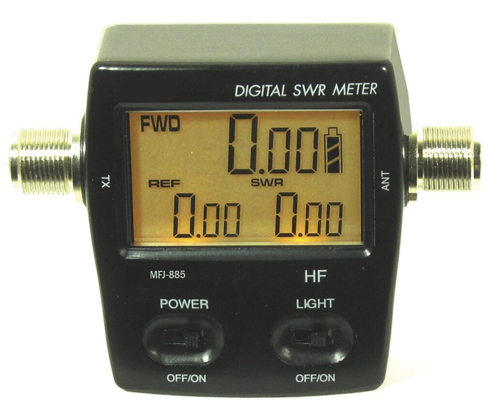
    If you want to monitor you system’s performance, a good SWR (standing wave ratio) meter is a key piece of hardware. With a quick glance at the meter, you can see how your radio, coax and antenna are working. SWR meters come in many shapes, sizes, and styles.

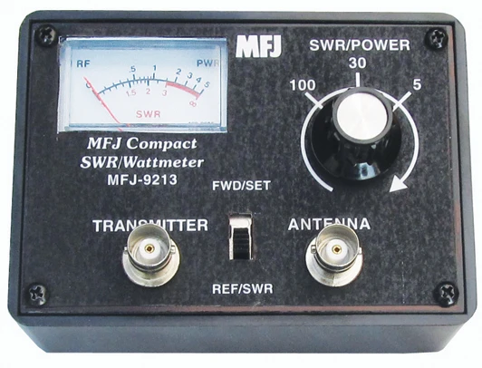
    Direct reading meters such as the MFJ-9213 can be identified by a FWD-REF switch and a common dial with a single needle. These meters require the user to set the switch to FWD (forward power) and then push the microphone PTT button and stay in the transmit mode while adjusting the meter to the SET or CAL line on the meter. Then release the PTT button, set the meter to REF, and key the microphone again while reading the SWR value on the meter.

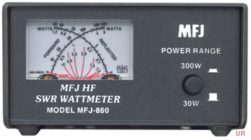
    Dual or cross needle meters such as the MFJ-860 require no adjustment. Push the microphone PTT button and one needle will show the power output, while the second needle will show the reflected power. The place on the meter where the needles cross indicates the SWR.

    Digital meters such as the MFJ-845 require no adjustments and are the easiest to use. Just push the microphone PTT button and directly read the values from the digital display.

    So what does this thing tell me? It will tell me if my transmitter is putting out the correct power. It will tell me how much of that power is being reflected back to the transmitter and it will tell me how well my antenna system is matched to the frequency I am using.

    One very important detail about SWR meters is that they are frequency specific. Using an HF meter to test UHF frequencies will result in bad readings. So always make sure that you are using an SWR meter that matches the frequency you are transmitting on. There are many of the old CB meters out there – but remember they were made to monitor frequencies around 27 Mhz and do not work well on other frequencies.

  • Hardware 101: Amp Meters

    Is your radio acting strangely? Coughing? Runny antenna? Watery display?

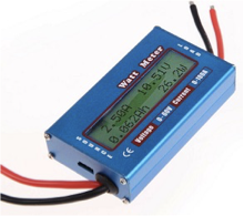
    A quick way to check its overall health is with an amp meter. If power is going out, then your radio will be sucking power in! The amp meter is the thermometer of the radio world.

    A quick review of your manual will tell you what your radio consumes when putting out full power. Most mobile radios will consume 20-22 amps.  So don’t hesitate; if your radio seems sickly and you think it’s got the coronavirus, stick an amp meter in its mouth and key the mic and see if its temperature is normal. 22 amps on the meter? It’s not a virus!

    If your 700 amp, klystron powered, 473 pound linear (another topic for another day!) power supply does not have a built in amp meter, you can certainly find one, like the one pictured here, on Ebay for around $10. A quick set of Anderson power pole connectors on each end and the doctor is ready to check radios!

  • WebSDR

    Are you locked down and looking for things to do? Visit WebSDR.org and listen in on hams all over the world. With WebSDR you will be able to take control of receivers worldwide and tune in on all of the bands in all of the regions. Someone not interested in ham radio (that can’t be us!) activities? Then tune in to the European stations and brush up on your French language skills.

    It’s as easy as starting up your computer and going to www.websdr.org.

    • Scroll down the main page and you will see ham stations from all over the world.
    • Pick a region
    • Pick a station
    • Pick the band you would like to listen to

    It’s that easy! You’re in control. Scan the waterfall (now you know what that purple thing up there is called!) and pick out the strong stations as they will be the brighter vertical lines. You can also try the weaker stations as shown by the faint lines. Or maybe the whole band is quiet with no lines at all – just change bands and keep going! Hear something rare or exotic? Create a log on your favorite SDR site and log in your treasure.

    Want to practice your CW? Tune down to the low end of the 40CW band and find a station; they are always there! Want to practice more later? Then just start the audio recording and play it back at another time.

    So, while locked in, stay out of the cookie jar and junk food, and go play in SDR land!

  • June Hardware Workshop Date Change

    A number of people have indicated they can’t attend the hardware workshop on June 2 due to a conflict with Sea-Pac. I am going to move the hardware workshop so that members can attend Sea-Pac and still be able to attend the workshop.

    The hardware workshop will now be from noon until 4 PM on Saturday the 16th of June at the same location. If you would like to attend, please email me (training [at] multnomahares [dot] org). I hope this is a better date for everyone.

  • Hardware Workshop

    On Saturday, February 24 from 12:00 to 16:00, I will be conducting a Hardware Workshop. This will be a show and tell type session with plenty of hardware to touch and talk about! There will be a presentation about many of the different types of hardware used in ham radio stations, what they do, and when you need or don’t need them. Some of the items will include antenna tuners, TNCs, antenna switches, SWR meters, amplifiers, keyers, antenna analyzers, and many more.

    After the presentation, there will be a Q&A session, then some additional time to actually see various pieces of equipment.

    Attendance will be limited to 20 attendees with priority given to active MCARES members although all hams or interested parties are invited if space permits. Contact training [at] multnomahares [dot] org to sign up and get location details.

    This session will be repeated on June 2.

  • Featured Member Profile: John KI7LYP

    Originally licensed as WN7ULT when I was 13, I have always had an interest in radios and electronics. My hobby and ham radio lead me through school and into a career in the US Navy working on communications and radar equipment. My entry into the Navy was busy with boot camp, dating and marrying my wife Patti KB7GMM, but then things settled and I returned to ham radio with my new Tech license WH6AVQ.

    I finally worked up my CW speed and upgraded to General class (KH6XG) and, with the new privileges and also a Navy MARS license, I spent many hours, both on ships and ashore, running phone patches for sailors all over the Pacific as well as working the DX stations and acquiring quite a collection of QSL cards from all over the world (my favorites are still my QSL cards from the islands of Vanuatu and Naru).

    After retiring from the Navy, I continued to work in computers and electronics and to this day, I still enjoy finding and repairing old communications equipment.

    In late 2015, I was recruited into the Multnomah County ARES group, and I finally gave up my well used Hawaiian call and went back to a 7 district call, KI7LYP.

  • J-Pole Antenna Workshop

    If you would like to build your very own J-Pole, here is your chance! On Saturday, February 3, I will conduct a workshop where participants will build a copper pipe J-Pole antenna for the 2-meter band. This is the antenna build we demonstrated at the November, 2017 General Membership Meeting.

    There will be a fee of $15.00 per person to cover the cost of materials. Space is limited, and advance registration is required so we can procure materials. Contact training [at] multnomahares [dot] org to sign up.